")
")
RSP Techonology is offering a new concept in global control system and remote management of fuel tanks: the S2 Safety System. S2 System is designed to manage the entire chain of fuel resupply order online and totally unassited.
Integrated Solution - The S2 Safety System consists of a set of equipment, integrated allow broad control of operations involving the supply, storage, input and output of liquid fuels resellers.
To meet these goals, the S2 System has numerous functions, technological resources, contemplating the submission of data management and administrative key to achieving operational control dedicated to the general trade in liquid fuels, enabling better, faster and more precise analysis of the wide range information, require the competitive market.
Thus, the S2 Safety System is in a much more complete and comprehensive than a simple sensing a measurement system, presenting itself as a global system of operational management and control of all the steps that comprise the suply process and suply of liquid to a dealer.
S2 System Equipments
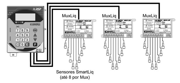
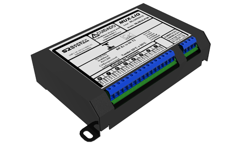 MuxLiq
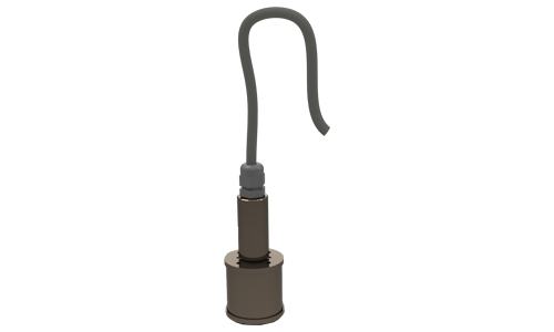
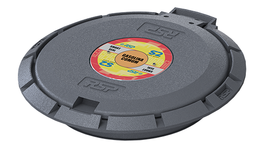
- The SmartSeal is a device that operates as an eletronic access to the tank by controlling the effective input and output of product, preventing unauthorized access to the tank. With the same dimensions as a conventional lid, Smart Seal is easily installed on the track;
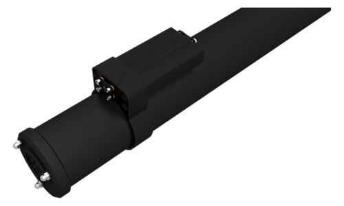
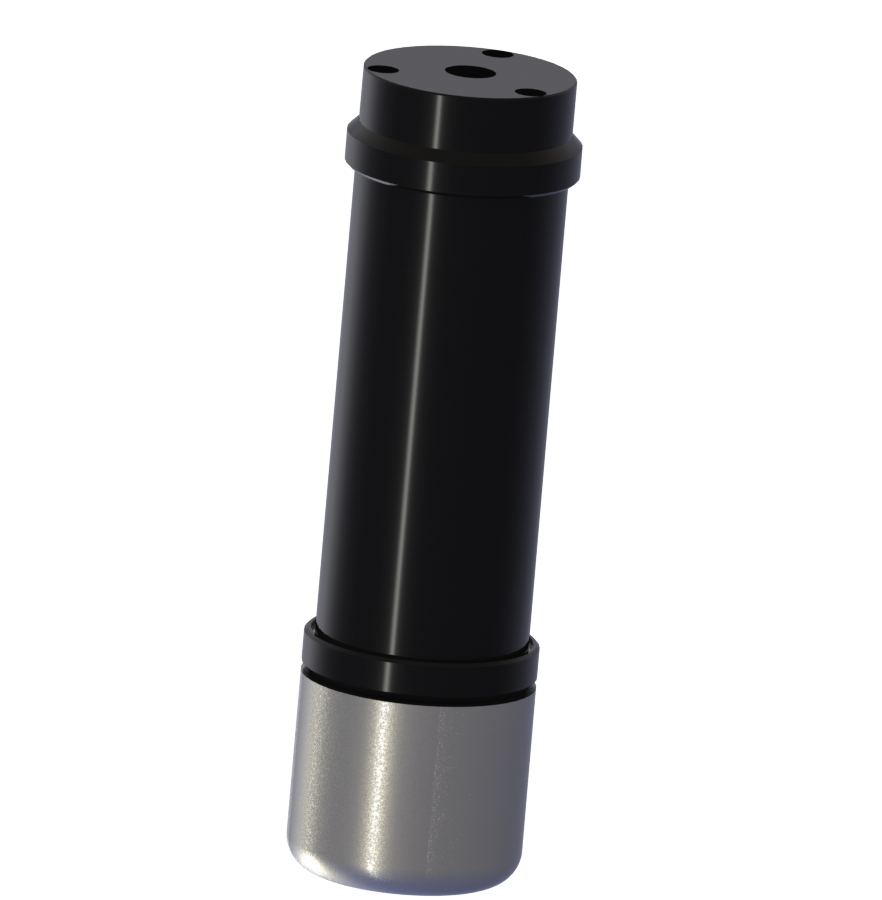
- The SmartProbe is designed to accurately measure the volume of stored product. When coupled with proprietary technology Croma ID allows the minor differences are detected in the marking of fuel;
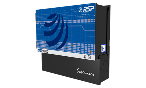
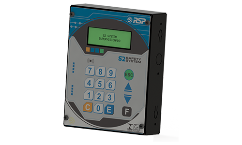
- The Supervisor is installed in the office and constitutes the main element of S2 control, running all supervision of the devices that compose the system. One of its functions is to process the information sent to the central control and integrated data management;
- The MuxLiq operates as a hub of intelligent sensors for liquids. With its use, allows a reduction of up to seven times the distance of the cables used in a conventional installation;
- The SmartLiq is the sensor that singals the presence of liquids. Installed in the interstices of containment tanks or cameras can be connected to any of the S2 devices: Seal, Probe or MuxLiq;
- The SmartConsole is the remote Supervisor console. Installed on the track, their use enables local operation of the system without the need for access to the access.
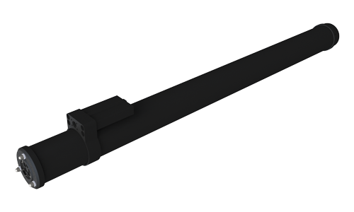
- The Probe Radar consists in a device with radar technology. It should be used for tanks with diameter more than 4 meters (12 feet). Can be used in conjunction with SmartProbe in the same plant;
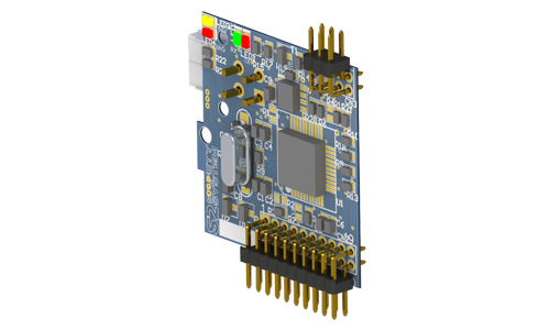
- The Ibox is a logical board designed for security and handling encryption keys. Equipped with secure and dedicated processor, it is essential for operation in environments that require safety information and tax requirements;
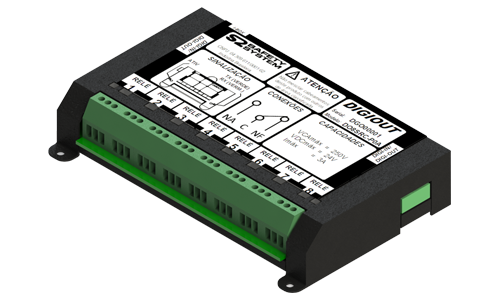
- The Digiout is a device capable of allowing a control drives and control supervisor. Integrated into the software, can be configured through a specific application to perform a set of operations on a fully unattended sites based on information collected in other devices such as volume, temperature, level and others;
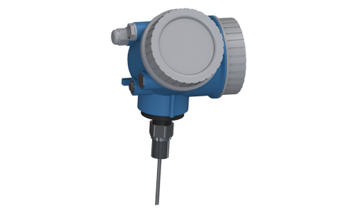
- The Smart Thermo is a temperature probe with continuous temperature monitoring and tracking. It can be used on tanks of up to 45 meters, and performs the measurement of temperature digital form with a resolution of 0.0625 °C (0,1125 °F).
S2 System Software

The S2 System basic concept is present information through any browser open within S2 Supervisor network. With Browser, you can obtain an intuitive and graphically all S2 System's operating facilities. To perform all monitoring functions, control and registration of information.
There are two modes Control System S2: the Advanced and Premium, each one having ideal tools for managing your business. The system has several features that enhance your gas station management. It is possible to obtain operating data from all integrated equipment, historical volumes, smart seal control, product level, fuel quality, discharge records, stock charts, and more. Alerts can be sent via SMS, reports or accessed in you mobile phone.
With a modular design, additional control features can be added, such as Fleet Control, Controlled Pump Calibration, and integration with industrial systems. It supports several forms of connection to exchange information, either through physical communication ports (network, serial ports or parallel ports, USB) or via TCP / IP connections, DDE. With this, all the information received from the systems connected to the S2 System will be available and managed in the same way that the information collected by current systems.
The Data Management Integrated Center combines alarms information providing data access only for authorized users, getting reconciled information from all service stations. Information can be retrieved in real time, dynamically interacting with each service station.
In a simple way, product delivery operation may be authorized with automatic registration of all steps. Also, through a simple smart phone covers can be locked or unlocked.
Put in your hand instantly valuable information as inventory volumes, sales and delivery. Emergency situations are also monitored in a real time. Leaks, unauthorized openings or equipment violations are reported immediately for effectiveness decisions.

Ecologic II is specially designed to monitor liquid sensors (like SmartLiq) installed in a gas station plant. It executes continuous monitoring with alarms indicators and historical data in memory. Leak conditions and other status are shown in a simple and direct way.
The figure below illustrates the default installation topology of a Ecologic II system:
Ecologic Versions
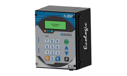
- The Ecologic EC2 has been specially designed for the Environmental Monitoring gas stations, which monitors several liquid sensors of the forecourt;
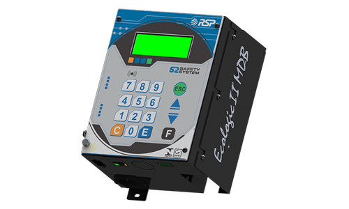
- The Ecologic MDB is highly compact and robust Environmental Monitoring, including as a native protocol the Modbus standard. Is the best way to interface with BMS and PLC’s.
System Peripherals
- The MuxLiq operates as a hub of intelligent sensors for liquids. With its use, allows a reduction of up to seven times the distance of the cables used in a conventional installation;
- The SmartLiq is the sensor that singals the presence of liquids. Installed in the interstices of containment tanks or cameras can be connected to any of the S2 devices: Seal, Probe or MuxLiq;

The MiniS2 was designed specifically to meet the cost-effective solutions for tanks gauge and environmental monitoring in an integrated manner. It allows connection of the same optical Smart Probes standard for best accuracy and control and using standard environmental sensors.
Installation
The probes should be installed in four-inch manholes.
The sensors can be installed in monitoring wells in double-walled tanks, sumps pumps, sumps tanks, and diesel filters.
Features
MiniS2 is the most compact and suitable equipment in the market. It executes continuous monitoring with alarms indicators and historical data in memory. Leak conditions and other status are shown in a simple and direct way. It allows direct operation in the console or via graphical interface through S2 Pilot application.
Mini S2 Versions
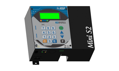
- The MiniS2 FRC is a highly compact and robust automatic tank gauge (ATG) and Environmental Monitoring. Using S2 Pilot you can access several function available in your PC. Using the same graphic interface of S2 System is the best way to manage and monitor you gas station.
- The MiniS2 MDB is a highly compact and robust automatic tank gauge (ATG) and Environmental Monitoring, including as a native protocol the Modbus standard. Is the best way to interface with BMS and PLC’s.
System Peripherals
- The SmartProbe is designed to accurately measure the volume of stored product. When coupled with proprietary technology Croma ID allows the minor differences are detected in the marking of fuel;
- The MuxLiq operates as a hub of intelligent sensors for liquids. With its use, allows a reduction of up to seven times the distance of the cables used in a conventional installation;
- The SmartLiq is the sensor that singals the presence of liquids. Installed in the interstices of containment tanks or cameras can be connected to any of the S2 devices: Seal, Probe or MuxLiq.
Comparative Table MiniS2 / S2 System
Comparative Table of Features |
System |
|
|
Mini S2
|
S2
|
|
|
Measuring Probe Capacity
|
1 to 6
|
1 to 48
|
|
Sensor Capacity (Enviromental Monitoring)
|
1 to 24
|
1 to 144
|
|
Seal Capacity - Electronic Tank Access Control
|
No
|
1 to 48
|
|
Seal Support - Electronic Tank Access Control
|
No
|
Yes
|
|
Fuel Quality Control - CromaID
|
No
|
Yes
|
|
Fleet Supply Control
|
No
|
Yes
|
|
Remote Management with Internet Access
|
No
|
Yes
|
|
Remote Data Storage (Cloud)
|
No
|
Yes
|
|
Local Data Storage (Deliveries and Stock)
|
4KB
|
64 GB
|
|
Data Conciliation and Information of Multiple Systems
|
No
|
Yes
|
|
Network Operation
|
Yes
|
Yes
|
|
Users in Simultaneous Using (1)
|
1
|
Unlimited
|
|
“Backup” Remoto de Dados (Nuvem) Remote Data "Backup" (Cloud)
|
No
|
Yes
|
|
Supply 95V~250V / 50Hz~60Hz
|
Yes
|
Yes
|
|
Battery (No Break)
|
Yes
|
Yes
|
|
20°C Temperature Conversion
|
Yes
|
Yes
|
|
Water Detection
|
Yes
|
Yes
|
|
Operation through Remote Console
|
No
|
Yes
|
|
Total of Users (1)
|
Until 5
|
Unlimited
|
|
Graphs and Moving Historic
|
Yes
|
Yes
|
|
Events, Deliveries, Sensors and Selling Reports
|
Yes
|
Yes
|
|
Supply Reports
|
No
|
Yes
|
|
Automatic Delivery Compensation
|
No
|
Yes
|
|
Integration with Smartphones (S2 Mobile)
|
No
|
Yes
|
|
Integration with Forecourt Systems (2)
|
No
|
Yes
|
|
Integration with Management Softwares (2)
|
No
|
Yes
|
| Nozzle Controled Calibration |
No
|
Yes
|
|
APO Emission – Automatic Product Order
|
No
|
Yes
|
|
Message Reporting by SMS
|
No
|
Yes
|
|
Message Reporting by E-Mail
|
No
|
Yes
|
|
Software Operational Mode
|
Installed
|
Browser
|
|
Operational and Informative Management Software
|
Pilot | Advanced or Premium |
Comparison with Software Premium
(1) Limited to Disk size and Network Capacity
(2) For Equipments homologated by RSP

Local Software Premium
The Software Premium allows your station or stations network to be viewed over the Internet. All data are to be reconciled in your network, allowing greater control over their information. It also has a wider range of device support and unique features depending on their Internet connection. This means that your company can instantly build a fuel logistics management on your network without need for high investments in development, creation and update of the platform, with only a low monthly payment.A number of essential services make up the Premium platform such as sending messages to cell phones to alert information (leaks, deliveries, low tank, etc..), E-mail, Control and automatic calculation of inventory optimization in the tank, making request / suggestion to buy, and many others.
Functional Appearance
- Increased storage of historical data (supports up to 1 years of information on local disk);
- Leak testing (programming);
- Probes with CromaID support locally;
- Forwarding data to Central;
- Integration with pump controller (always updated);
- Allows integration with RSP Protocol Management Systems (always updated).
Installation
The software is already installed on equipment, not being necessary any installation, only the licensing order of the system.
Update
Receive automatic update of your version by Internet, every deployment of new services and new devices.
Advantages
To use the Software Premium you need a connection to the Internet. This connection can be shared by station or can be a unique (3G, ADSL, Cable Modem). With the acquisition of the Software License Agreement Premium Site, the user will now have access to Central Premium software that lets you enjoy a number of features and essential facilities for the control of a Station network .
Support
Has the facilities of a Remote Support and On-Line Premium, which allows a diagnosis unique with personalized service by our technical team. Our team is trained to assist you and support your needs, so you have more control and can enjoy all the benefits of the S2 System.
Central Software Premium
Services offered by Central Premium mode are:
- SMS Sending;
- PAP Ordering (Automatic Product Request);
- Emails Sending;
- Central Login to access by multiple users over the Internet;
- Automatic Data Backup in Central Local;
- Commands sending by Central;
- Wap Central use to connect via Phones.
S2 Premium Images
Home Screen:

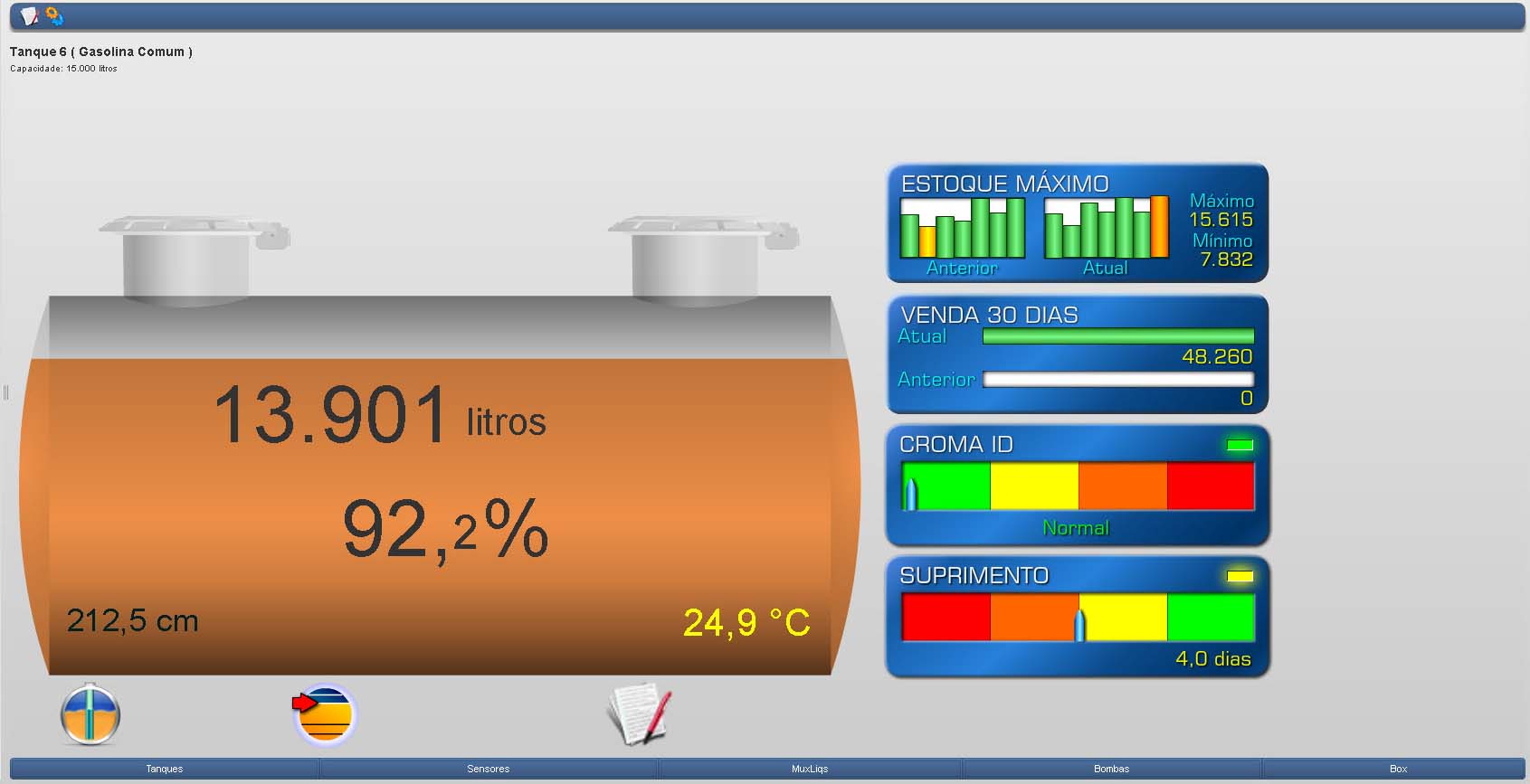
Tank Screen:
Refueling Query:

Pump Screen:

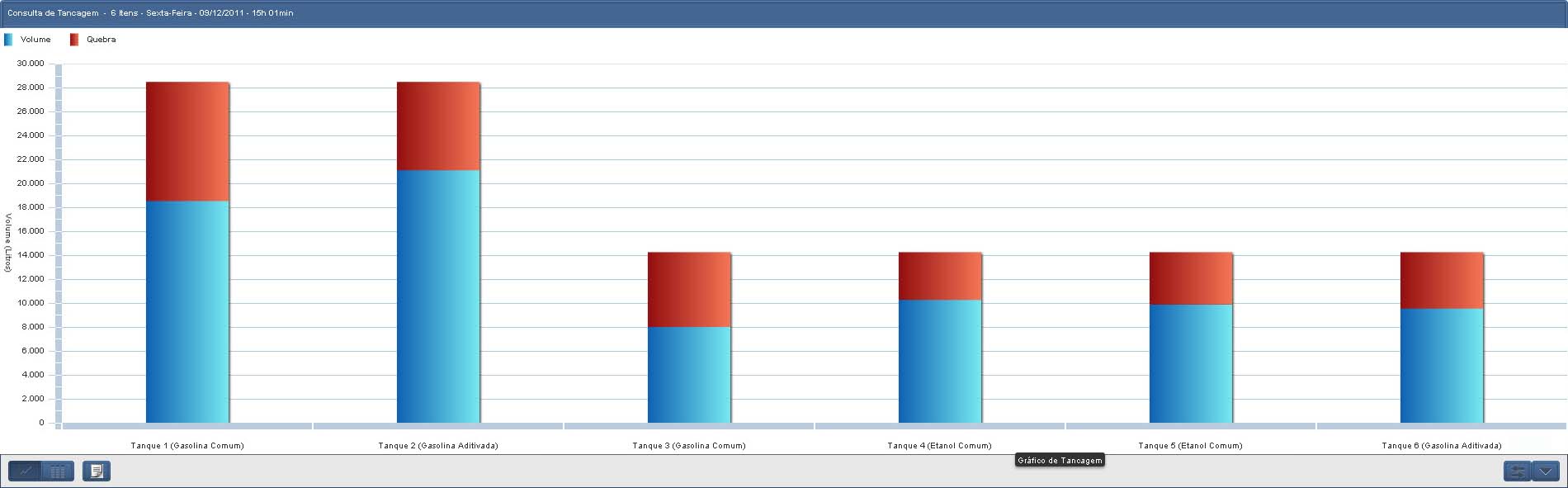
Tankage Query:
LMC and Forecast Sales Reports:


S2 Premium Features
|
Menu
|
Support
|
|
Historical
|
Refueling
|
|
Tank Calibrations
|
|
|
Deliveries
|
|
|
Totals
|
|
|
Tightness
|
|
|
Stock
|
|
|
Events
|
|
|
Sensors
|
|
|
Tankage Analysis
|
|
|
Sales
|
|
|
Reports
|
Refueling
|
|
Controlled Calibration
|
|
|
Totals
|
|
|
Tightness
|
|
|
Received Fuel
|
|
|
Deliveries Conciliation
|
|
|
Fuel Sales Conciliation
|
|
|
Daily Balance
|
|
|
Events
|
|
|
General Balance
|
|
|
Sensors
|
|
|
Sales - Pump
|
|
|
Sales - Probe
|
|
|
Tankage Analysis
|
|
|
Configuration
|
|
|
Configuration
|
Calibrations and returns
|
| Site | |
| Tanks | |
| Products | |
| MuxLiq | |
| Console | |
|
Sensors
|
|
|
Installation
|
|
|
Operation
|
|
|
Invoices
|
|
|
Programmable Seal Unlocking
|
|
|
Programmable Tightness
|
|
|
Transfers
|
|
|
Reboot Supervisor
|
|
|
Users Register
|
|
|
Add/Delete Users and Profiles
|
|
|
User can change his Password
|

It consists the S2 System local software with features similar to Premium software, including the following points:
Software Advanced Features
- Historical Data Storage (local deliveries of the last 61 days);
- Stores the last 30 deliveries;
- Integration with pump controller;
- Allows Integration of RSP protocol with systems management;
- Performs Fleet Control;
- Performs Controlled Test Measure;
- Do not use Internet.
Licensing
The Advanced software license agreement is final and is purchased with the equipment. Thus, it is a powerful tool to manage their logistics in your Gas Station.
Central Access
Advanced Software is designed to work exclusively in the environment of the Station, so all the viewing is done via the local network of the post, or directly by connecting a network cable.
Software Expiration
The Software don't waste validity, it remains unchanged throughout its use.
Installation
The software is already installed in the equipment, not being necessary any installation.
Updates
Being a definitively software license, there are no automatic updates for the version. If you are interested in combining data from a network of Stations and access them via the Internet at any point, see here how Premium Software licensing.
Support
Have an exclusive channel of contact by email to clarifying their doubts.
Please direct your questions to This email address is being protected from spambots. You need JavaScript enabled to view it. or preferably use the existing form on the website in the Support area , Technical Assistance option , which will guide in order to enter all the information needed to better care.
S2 Advanced Images
Tank Screen:

Sensors Screen:

Pump Screen:

Deliveries Table:

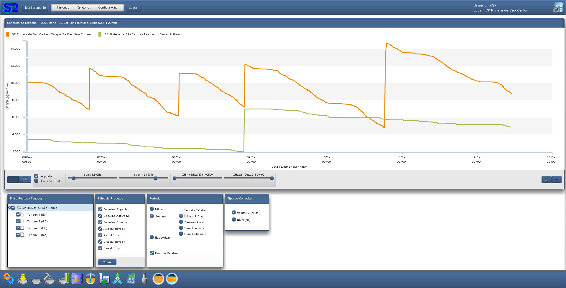
Stock Graph:
S2 Advanced Features
|
Menu
|
Support
|
|
Historical
|
Refueling**
|
|
Deliveries**
|
|
|
Totals*
|
|
|
Stock**
|
|
|
Events**
|
|
|
Sensors
|
|
|
Sales**
|
|
|
Reports
|
Tank Alerts**
|
|
Deliveries**
|
|
|
Fleet Control
|
|
|
Totals*
|
|
|
Events
|
|
|
Balance*
|
|
|
Sensors
|
|
|
Sales**
|
|
|
Configuration
|
|
|
Users
|
|
|
Configuration
|
Calibrations
|
| Database | |
| Fleet Control | |
| Documentation | |
| Invoices | |
| Transfers | |
|
Restart Supervisor
|
* - Up to 61 Days Past
** - Up to 61 Days Past or the last 30 Events

The S2 Mobile is an application that allows your station or network of stations be viewed by any phone with Android or IOS system. All data will be reconciled to your network, allowing greater control of their information. It is an application developed specifically to view and control simply via a SmartPhone or Tablet. The S2 Mobile maintains the same visual identity offered in S2 platform, enabling rapid learning and ease of operation.
Features
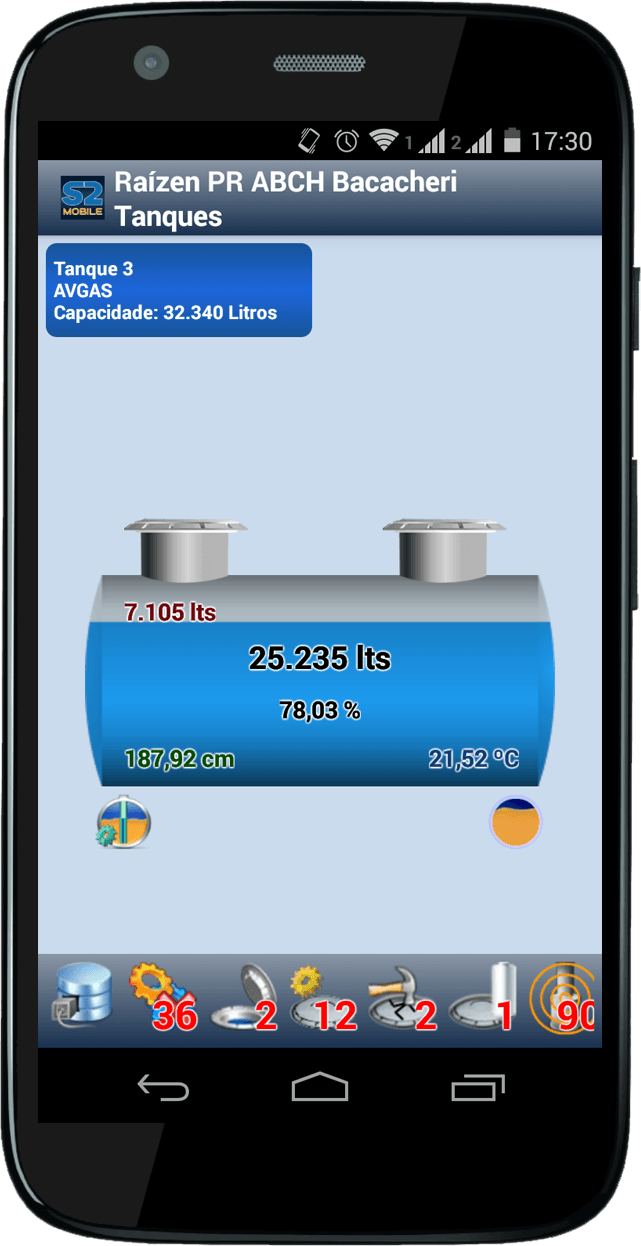
- View of the tanks and their volumes;
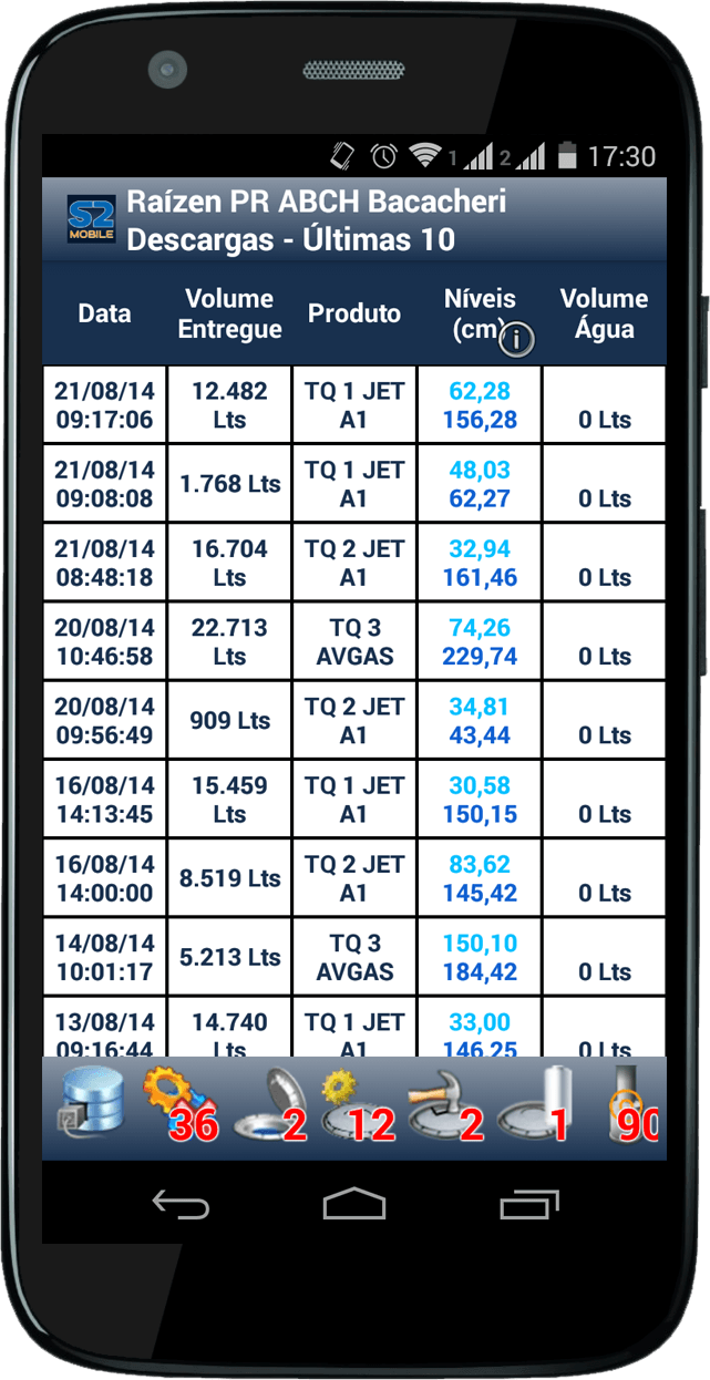
- Access to the latest 10 deliveries, containing all necessary information (Date Time, Volume delivered, volume at 20 ° C, etc.);
- View CromaID Standards;
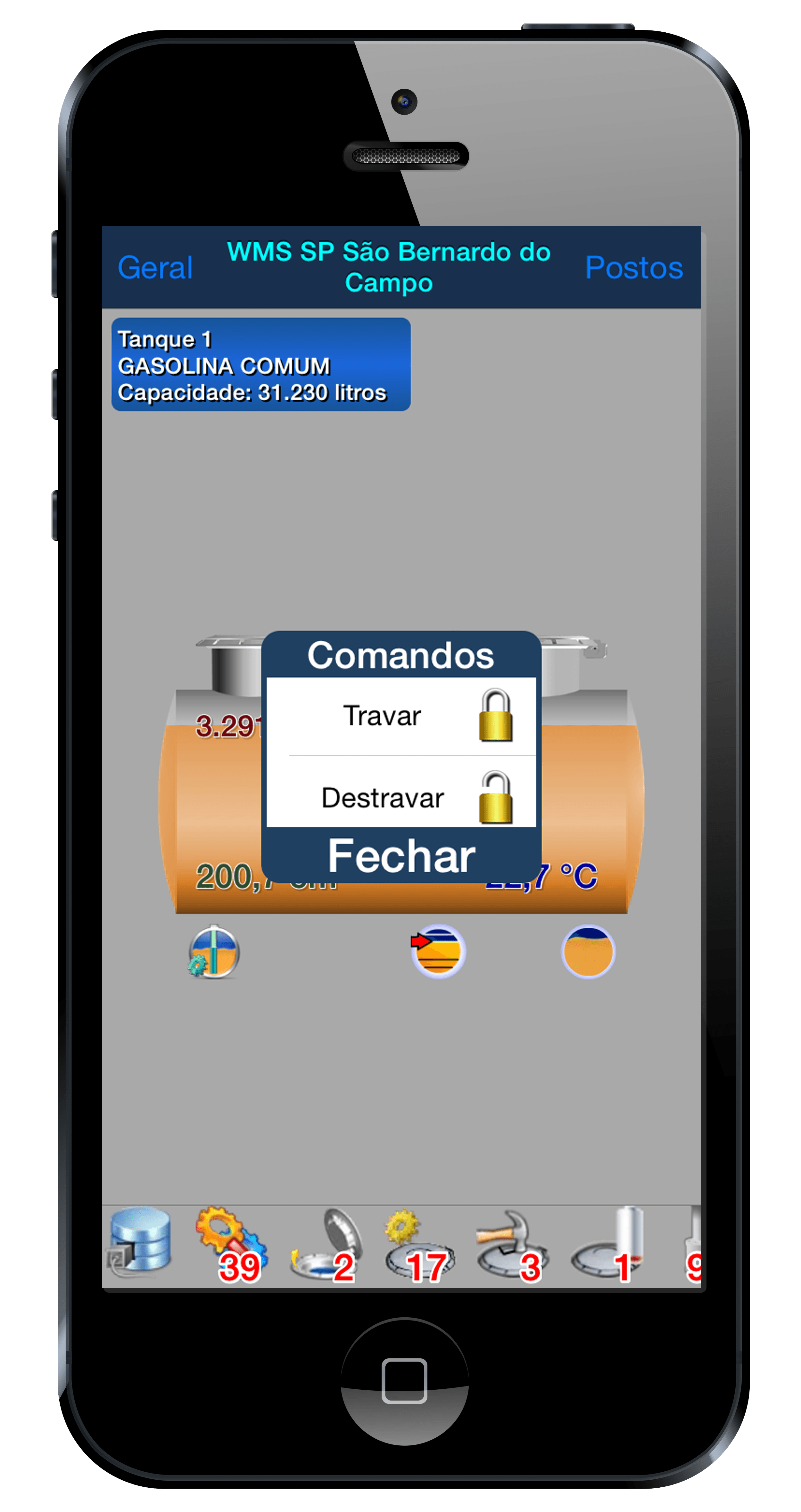
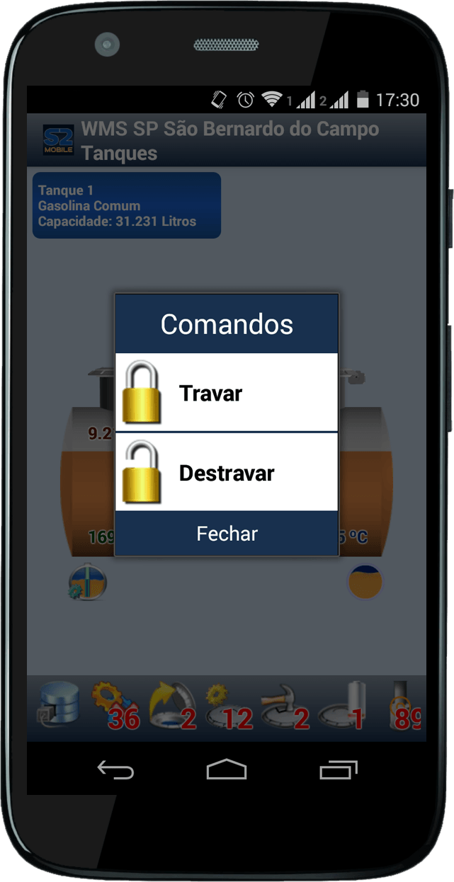
- Commands of Locking / Unlocking (Smart Seal);
- Diagnostic information (operational status, alarms violations);
- Displays the status of the liquid sensors;
- Notifications in the top bar of your Smartphone or Tablet, indicating information deliveries, sensors with alarms, Low Level Tank, etc..
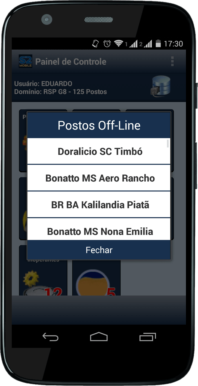
- Local Connection or Network with a simple amendment to Login.
Installation
For Android system, the app is available in Google Play Store. Simply access by Smartphone or Tablet and search for "S2Mobile".
For Iphone system, the app is available in Apple Store. Simply access by Smartphone or Tablet and search for "S2Mobile".
Local Connection
To use the S2 Mobile for local viewing in the Station, just be a Wi-Fi network allowing connection of these devices.
Remote Connection
The S2 Mobile also enables your field is accessed through an internet connection. Refer to Software mode to obtain a Premium Domain for your network.
Images S2 Mobile Apple
|
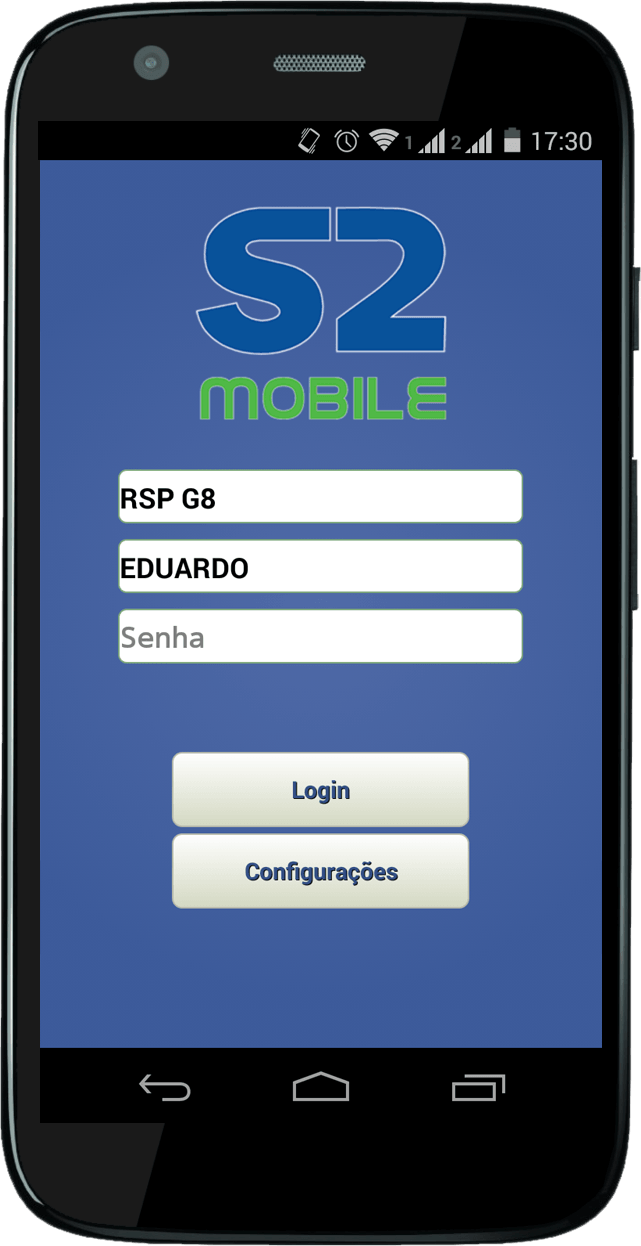
Login |
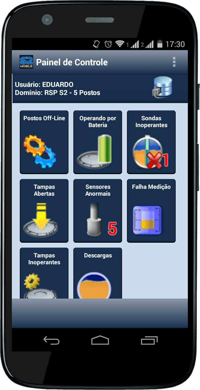
Control Panel |
|
Tank Screen |
Deliveries Screen |
|
Seal Locking Command |
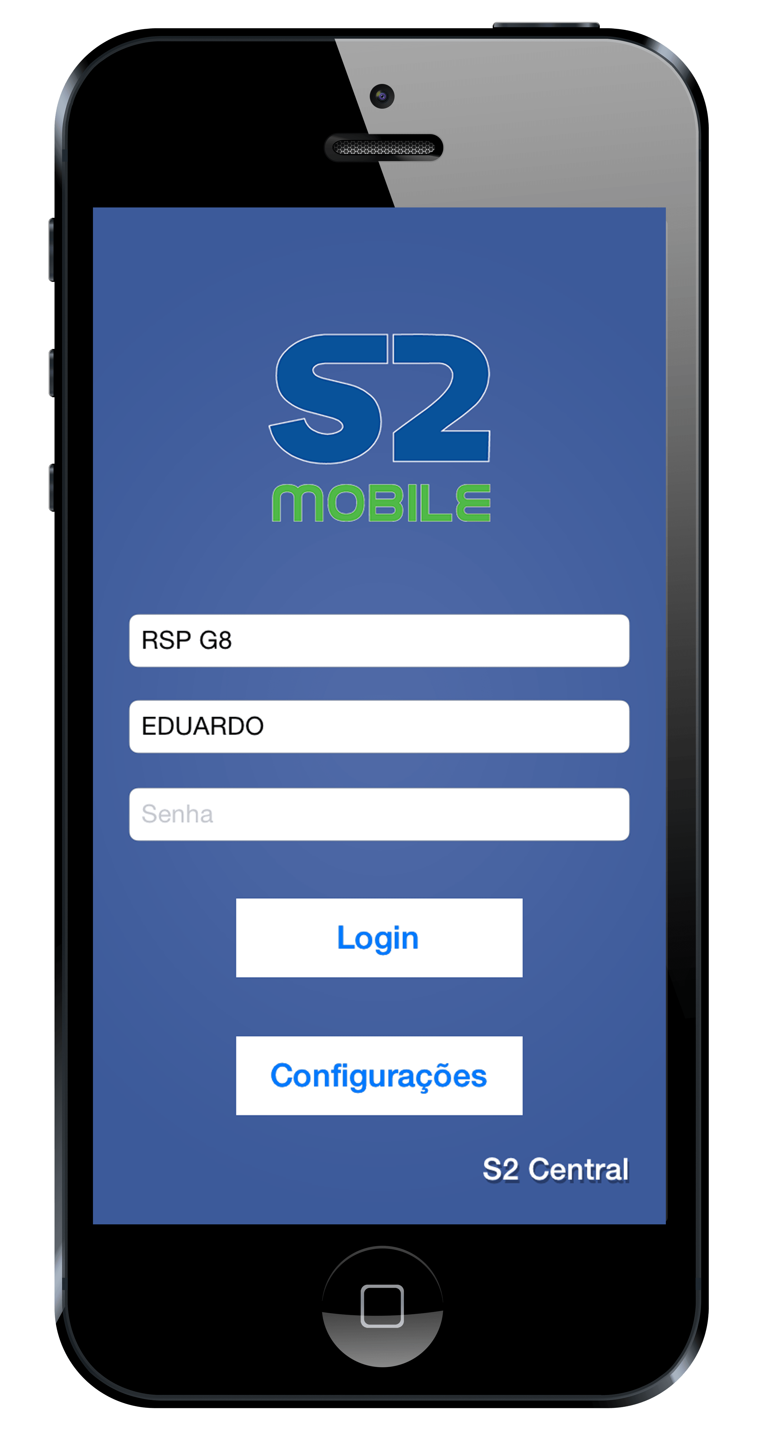
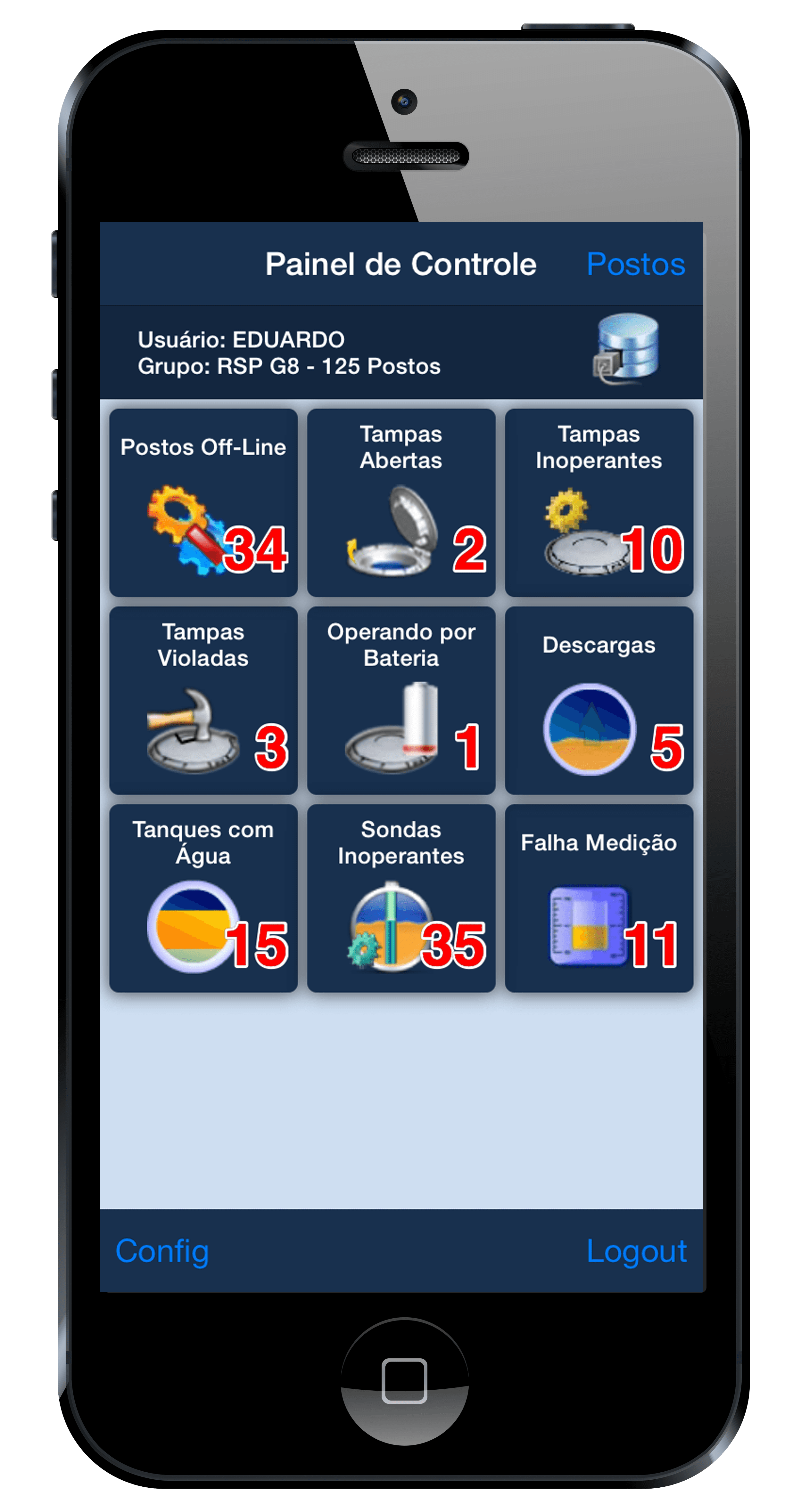
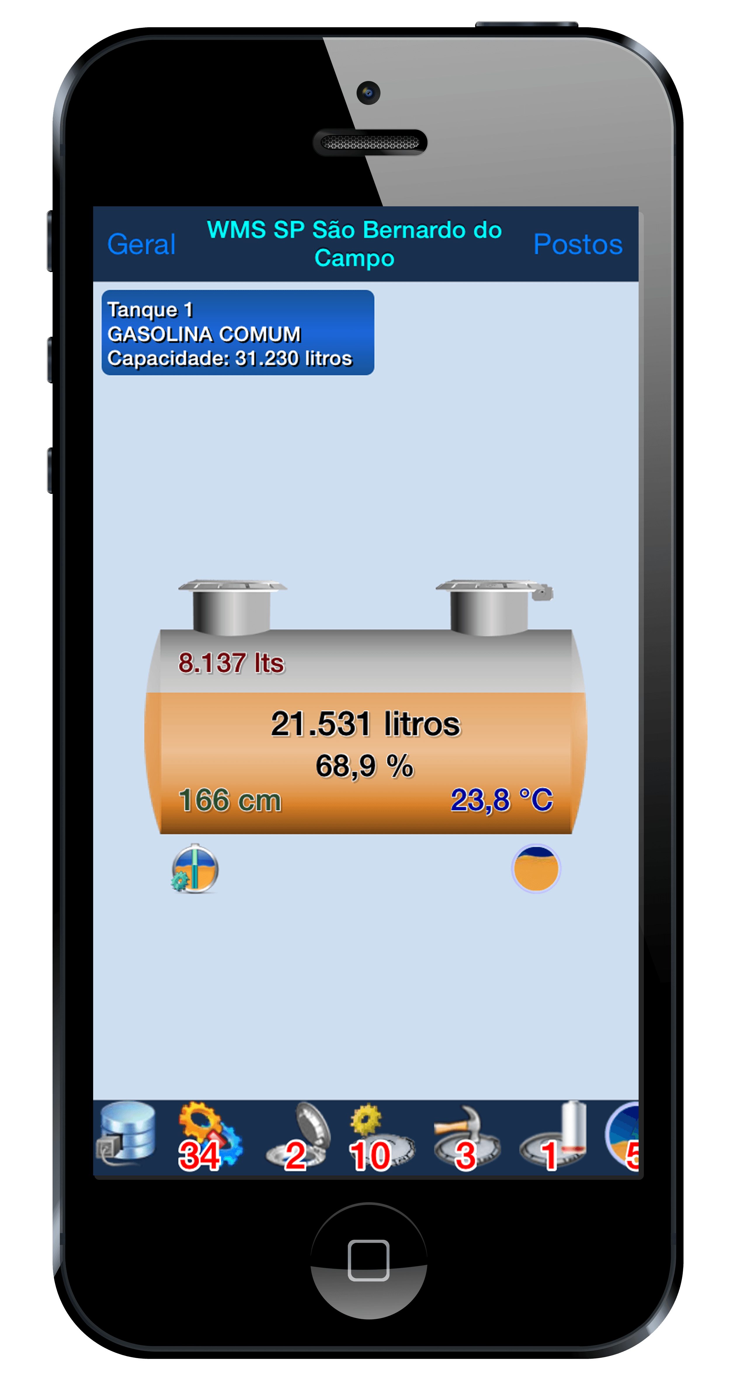
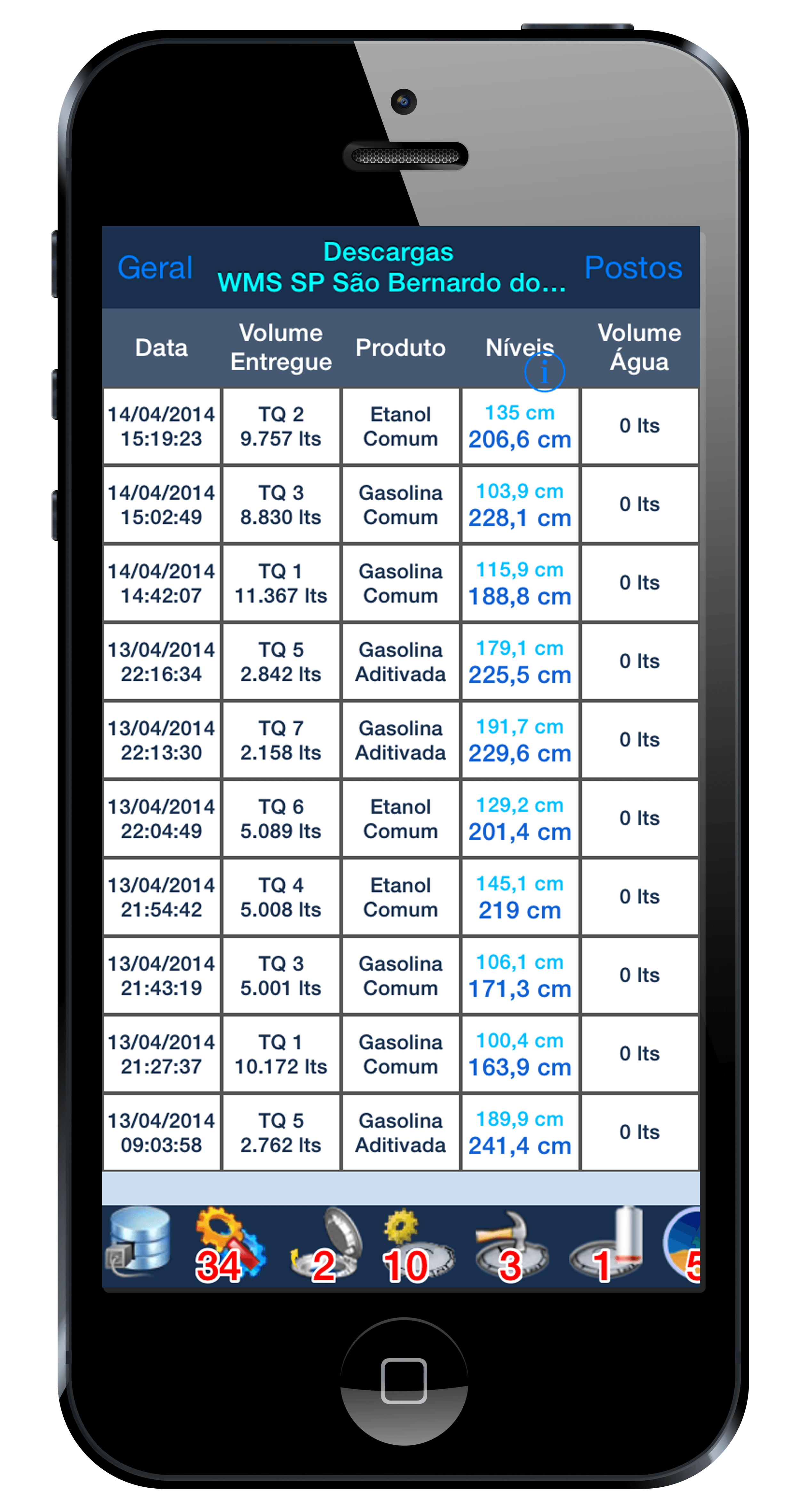
Images S2 Mobile Android
|
Login |
Control Panel |
|
Tank Screen |
Deliveries Screen |
|
Alarms List |
Seal Locking Command |
Additionally to all the tank gauge capabilities and environmental protection, S2 System can be transformed into a complete control system for industrial plants where it becomes necessary a control logic based on the tank information like level, volume or alarms.
Applications
In some plants, there is a fundamental requirement to control pumping and filtering that must operate under certain conditions. Operations such as spare tank filling, Diesel dialysis , etc. require continuous measurement and real time integration integrated and controlled by a PLC (Programmable Logic Controller) or a Supervisory System (SCADA, BMS) to perform operations automatically and in a safe form. In fact, it can be used ModBus protocol to interface with PLC or SCADA system. In plants that don't have supervisory system, the LPS Module (Programmable Logic S2) allows do this control without standard PLC equipment, in a competitive way, without need hiring expensive teams to programming these systems in Ladder language.
LPS Module
The LPS module consists of special module cards with outputs placed on S2 that will perform the control logic of the fully integrated plant. The IBOX card, can be responsible for managing up to four output devices named DIGIOUT, where each DIGIOUT board could drive 8 port. In this fact, there is the possibility to control up to 32 output ports that can be connected to controlled devices like pumps, valves, etc. For more information, see the detailing on the IBOX and DIGIOUT.
Connection Mode

Principle of Operation
With this additional boards, you can define the logic through simple logic equations intuitively, using mathematical operators known as _AND_ _OR_ _NOT_. The visual interface provides a logical grouping for better understanding, giving an intuitive manner to define the desired logic.
Control Logic Example
See how you are extremely simple write an expression to operate lung tank filling on a system with three tanks, two solenoid valves and a pump.
Where:
VALV1 and VALV2 is the outputs corresponding solenoid drive valves for control of the Tank 1 and Tank 2 respectively.
PUMP corresponding output corresponds the motor driver of the product transfer pump.
NIVELBAIXO_TQ1 , NIVELALTO_TQ1 , NIVELBAIXO_TQ2 and NIVELALTO_TQ2

Note that variables are related to low and high levels defined for the Tank 1 and Tank 2 with SmartProbe measuring. Note that are only three basic mathematical expressions,to express the control logic, without knowledge of PLC's programming logic .
The Modbus Interface is a software module that can be added to the Supervisor to interface with Supervisory Systems and Programmable Logic Controllers (PLC). In this fact, BMS (Building Management System) has the facility to integrate tank gauging tank information and environmental monitoring system.
Using MODBUS protocol, it allow connections to systems like SCADA (Supervisory Control and Data Acquisition) and PLC (Programmable Logic Controllers).
S2 System can send information to a SCADA or to a PLC required only to be connected in the network. In all situations the S2 system always acts as Slave, providing requested information. The Modbus protocol support is provided in the S2 Interface module software.
If direct control is needed (without PLC) please check S2 System Programmable Logic module and associated electronic boards designed for this operation. S2 Modbus interface allows connecting either a network node or via a RS 232 serial communication so as to provide integration with many common PLCs.
Principle of ModBus Interface
You have to install the IMB application interface (ModBus) and connect to a PLC.

Applications
In some plants, there is a fundamental requirement to control pumping and filtering that must operate under certain conditions. Operations such as spare tank filling, Diesel dialysis , etc. require continuous measurement and real time integration integrated and controlled by a PLC (Programmable Logic Controller) or a Supervisory System (SCADA, BMS) to perform operations automatically and in a safe form.
Connection with Modbus Protocol
Using Modbus RTU protocol (Ethernet) or Modbus IP protocol, the Supervisor maps all information, emulating a PLC Record. The configuration parameters allow Supervisor to integrate with another PLC with the definition of the types of communication, device, doors, etc.
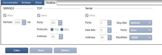
The S2 system even allows the co-existence of two simultaneous connections in MODBUS protocol, one in TCP / IP and other standard RS232 serial mode, operate in redundant to meet requirements in mission-critical systems.
Device Mapping
For data collection, the supervisor will keep information in a mapped form and may be read by any Supervisory System in a simple and direct way.
|
Device
|
Initial Reg.
|
Final Reg. | Number of Reg. | Number of Devices | Observation |
|
Gross Tank Volume
|
30,000 | 30,047 | 48 | 24 | Probe 1 to Probe 24 |
|
Tank Level
|
30,074 | 30,121 | 48 | 24 | Probe 1 to Probe 24 |
|
Product Temperature
|
30,148 | 30,171 | 48 | 24 | Probe 1 to Probe 24 |
|
Water Kevel
|
30,222 | 30,245 | 48 | 24 | Probe 1 to Probe 24 |
|
20° Volume Tank
|
30,296 | 30,343 | 48 | 24 | Probe 1 to Probe 24 |
|
Probe Status
|
30,370 | 30,393 | 48 | 24 | Probe 1 to Probe 24 |
|
Sensors Status
|
30,444 | 30,539 | 96 | 96 | Probe 1 to Probe 96 |
|
Supervisor Status
|
30,570 | 30,570 | 1 | 1 | Supervisor |
Description
The Fleet Control is a feature of the S2 System designed to enable the identification of each supply and held it hold a Fleet or Attendant Control.
For identification of supply is essential that there exists a hardware (pump concentrator) to hold control of the pump associated with reading a specific identifier that is installed in each nozzle.
This identifier can be an RFID reader card reader or a default buttonId.
See RSP to verify the approved equipment that perform this function.
Functionalities
The Fleet Control exists in S2 allows basically two types of specific controls :
- Control Attendants
- Control Supply Fleet(s)
The Control Attendant is only used when you want to control the sale and the cash generated by the operation of the attendant station .
The Fleet Control Supply is designed to control a fleet (Set of vehicles and drivers belonging to the same company), or even a set of fleets that carry supplies in the service station.
For the service point you want to just control the Attendant, the operation is simple , needing only to sign up for pre - authorized to make supply Attendant, and assigning a card to each of them .
For the Fleet Control, besides the registration of attendants, the system allows you to track and report detailing the Driver, Vehicle and Supervisor of Station. This operation is more complex and requires a number of records of drivers , vehicles and type parameterization to define quotas vehicle supply, utilization thresholds drivers , etc.
For who is Intended
The Fleet Control can be used by companies garages or gas stations, just by owning a fuel tank and supplying a controlled unit.
 |
 |
Total Integration
As the Fleet Control of S2 System is integrated with storage information, the user has a much more precise control of their inventory and their sales.
Due concentrators allow unique reading, the Attendant Control cannot be shared with the Management System.
Operation of Attendant Control
Operation of Attendant Control is simple and should be performed the following sequence for each supply :
- The vehicle parked next to a pump
- The attendant passes the card on the side of the pump where the vehicle is parked .
- The system identifies the registration of the attendant and waits the liberation of Hose.
- The Hose is automatically released by the system to supply the vehicle .
- After ending supply, the system generates a data record containing all data sourcing and identifying the attendant who supply the vehicle.
Operation of Vehicle Supply
There are various forms of operation in Fleet Control for Vehicle Control . The sequence below shows one of them .
- The vehicle parked next to a pump
- The driver passes the passes the ID card in the vehicle side of the pump where the vehicle is parked .
- The system identifies the vehicle on file , validates the constraints defined in the database , and if they are satisfied the conditions , release the hose to supply the vehicle .
- After ending supply , the system generates a data record containing all data sourcing and identifying the vehicle that carried supplies .
Attendant and Vehicles Control
The existing screens in the system allow registering a number of associated information and also the attendant to the vehicle such as make, color , plate and restrictions and releases set for each fleet or vehicle listing .
It can also be associated with a register of drivers in order to have a control not only vehicles , but also the possibility of control and restrictions of drivers .
Supervision
The system also allows the existence of a Track Supervisor and System Administrator that can be attribuited specific tasks, which will be verified in the case of Manual release , facilitating operation in situations of need for immediate release .
The registration screen has a number of specific tabs for the various registers of information .
- Registry of Companies
- Register of Employees (Supervisors and Attendant)
- Signups Driver
- Vehicle registrations
- Sign Up Profiles
- Registration Card
Reports
The system has a series of reports for analysis and control of the operation of the fleet. These reports have several filters that allow you to extract the data in a specific way with richer information.
The reports are:
- Report of Signups
- Reports Supplies
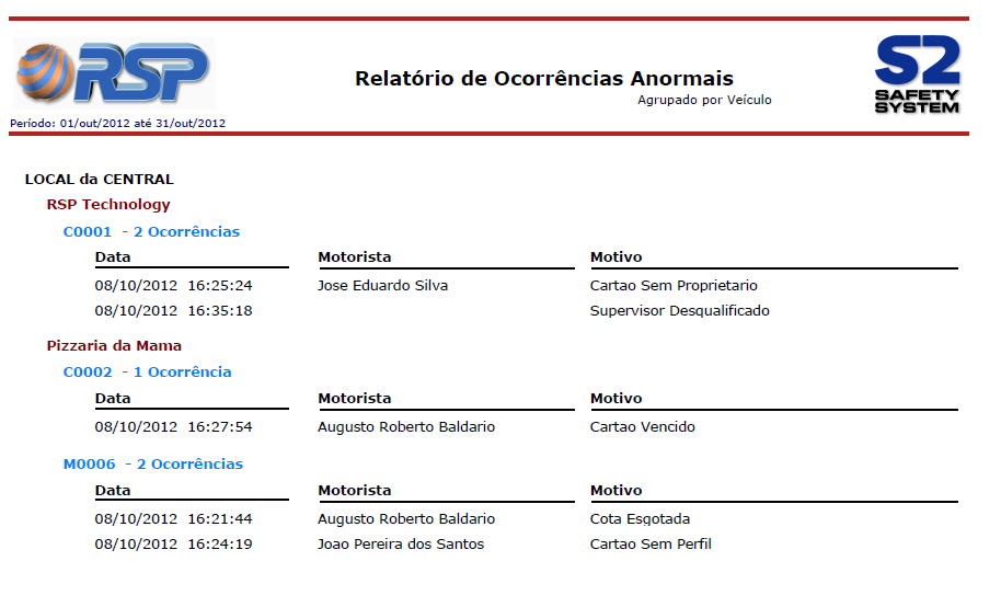
- Report Abnormal Occurrences
- Billing Report
- Report Parts and Services
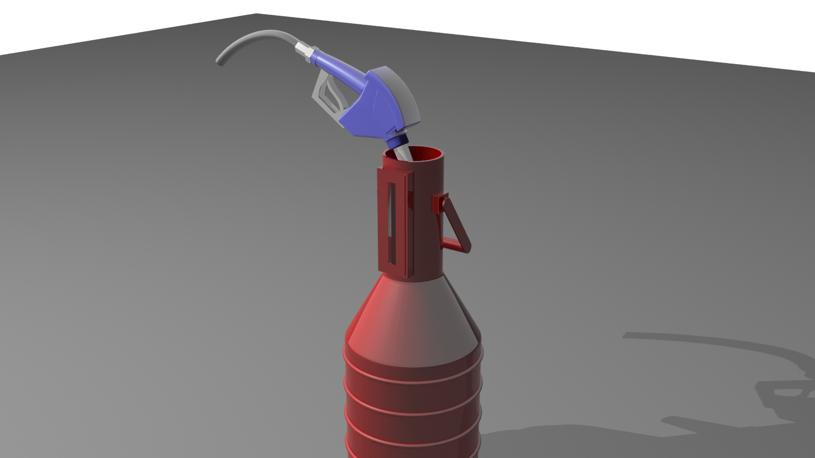
A Controlled Calibration consists of a unique feature of the Software Premium to help and record all calibrations operations performed on the Station. This prevents a large number of fuel deviations that are not controlled when used manual calibration, since operators could not necessary return product to the tank.
The Controlled Calibration is oriented by the SmartConsole (or in the screen) and guides the operator to do an assisted calibration operations. All actions are recorded for future viewing in several reports. To perform a controlled calibration, the system put the probe in fine reading mode, that allows evaluate minimal product oscillation inside the tank. Is important to say that fuel tank movements in and tank dimensions could create some inaccuracies. For a correct compensation a pump concentrator must be linked to the Supervisor.
Principle of Controlled Calibration
S2 System can monitor every step and verify if any operation abnormal. To do this, the operator has to make a selection of which hose should be used. This selection can be made directly on the console or in the system screen. In a same way, the operator must inform that he finished the calibration procedure. After that, system evaluates the time between start and finish calibration and validating all operation, making check of the correct product return to the tank.
The same hose can be used multiple times (for example, a calibration for low flow, high flow, and to one another for a conference) without needing inform the system. The report itself tells how many calibrations were performed in the period.
Operation Conditions
For a correct use of Controlled Calibration, some procedures must be followed:
- Previous Tank Calibration
The tanks must be previously calibrated (should have real measures launched in the tank register). Check if tank balance are among less than 0.3% value. If the tank is not correctly calibrated, some values may be distorted and you could receive wrong alerts.
- Probes Calibrated
The probes are automatically calibrated during use. For controlled calibration, must be ensured that the process of self-calibration is complete.
- Avoid tank dispensing at the beginning of the calibration
As a tank can have several hoses, it is essential that there is no sale in other hoses at the beginning. The system waits for all hoses in Ready status. An informational message is displayed to the operator if there is a hose dispensing that can avoid calibration.
- Correct Hose Register x Pumps x Tanks
The system uses the database of Hoses x Pumps x Tanks to decision control, blocking other hoses and increase the sensitivity of the probe from the. An error in this database make it impossible to check the measurement.
- Always finish the Measurement
The system waits for a long time (30 minutes) for end of calibration process of each hose. After the return the product to the tank, you should inform that the process has been completed. It may cause error if you do not terminate or perform product output during this interval.
- Diesel Tanks Calibration with Filters
The calibration process in diesel tanks that uses filters could have large deviations. Because the filter tank is not monitored, any leaks of product (due to faulty valves) or product removal is not accounted for, causing calibrations errors messages.
Detailed Report
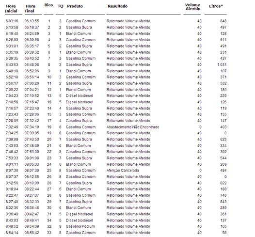
The list is sorted by sequence of calibration. See details of each column.
Start Time: Displays the time when the user begin the Hose Calibration
End Time: Displays the time that the user ended the Hose Calibration
Hose: Number of Calibrated Hose
Tank: Number of the tank in which the product must be returned
Result: System analysis of the Calibration Process
Calibrated Volume: Displays the total liters used during calibration (typically 20 liters for Low Flow test and 20 liters for High flow test)
Liters *: Indicates the total sold by the hose since the last Calibration. This information can be used to determine preventive maintenance of the hose.
Report Grouped by Hose
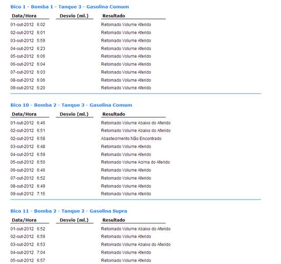
This report allows the analysis of deviations found in each hose. The values of deviations found in benchmarking should be entered directly into the system.
Report Grouped by Product
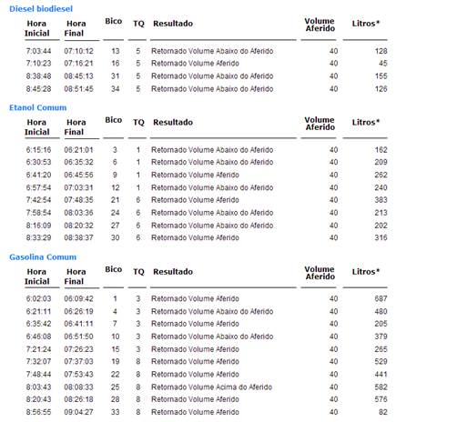
Possible results presented in the report are:
- Calibration Cancelled
Indicate that the hose calibration process was not completed. This can occur if the users manually cancel operation or because time expired (more than 30 minutes).
- Returned Volume Measured
Indicate that the volume returned is closer expected.
- Volume Returned under Measured
Indicate that the volume returned was under expected.
- Volume Returned above Measured
Indicate that the volume returned was above the expected.
- Supply not Found
Indicate that the calibration process has no record or the hose was not found. This can occur if the pump concentrator are not logically connected at the time of calibration, or if the calibration was closed manually via the console or the expiration of the time limit.
- Unexpected supply in the measured Hose
Indicates that a supply was detected in the calibration process is not compatible with the 20 liters standard.